Motor Controllers 101: Speed, Torque, and Control Basics
Understand motor controllers: how they regulate speed, torque, and direction with PWM, current limiting, and PID feedback, plus tips for selecting a driver.
Understanding Motor Controllers
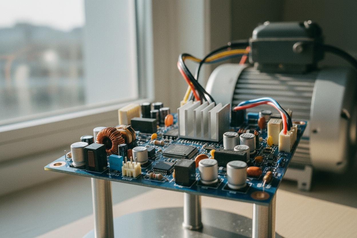
A motor controller is the bridge between low-power commands and high-power motion, converting control signals into precise voltage and current delivered to a motor. In the world of motors, controllers shape performance along three core axes: speed, torque, and position. Typical architectures combine a power stage (an H-bridge for brushed DC, a three-phase inverter for BLDC or AC machines) with control logic that measures and reacts to system feedback. Controllers regulate energy using PWM to adjust effective voltage, or by varying frequency and phase for AC and PMSM drives. Sensors like encoders, Hall sensors, and current shunts enable closed-loop control, while some designs use sensorless estimation derived from back-EMF or observer models. The load's inertia, friction, and disturbances dictate how aggressively a controller can accelerate without overshoot. Open-loop control is simpler but drifts under varying loads; closed-loop feedback holds setpoints with far better stability. Understanding the interplay between electrical inputs, magnetic fields, and mechanical outputs is the foundation for selecting, configuring, and safely operating any motor controller.
Speed Control Fundamentals
Controlling speed starts with the motor's natural speed–torque behavior and the load's profile. For brushed DC motors, average applied voltage (often set by PWM duty cycle) largely determines no-load speed, while increasing load introduces a drop due to back-EMF and winding resistance. A closed-loop PID controller compares measured speed from an encoder or tachometer to a setpoint, adjusting drive voltage to reject disturbances such as belt tension changes or airflow variations. Smooth acceleration and deceleration ramps prevent current surges, protecting both supply and windings. In BLDC and AC systems, speed is governed by electrical frequency; advanced methods like field-oriented control (FOC) manage torque-producing current while scheduling frequency to match the requested speed. Features like soft-start, coast, and dynamic braking shape transient behavior. Practical tuning involves setting appropriate loop gains, anti-windup, and filters to balance responsiveness with stability. The result is steady speed across varying loads, reduced mechanical stress, and improved energy efficiency in conveyors, pumps, fans, and mobile platforms.
Torque Control and Current Loops
In electromechanical systems, torque is fundamentally tied to current: T ≈ Kt × I. Effective torque control therefore relies on a fast inner current loop that commands and measures phase or armature current with high bandwidth. Controllers employ current sensing via low-side shunts, inline resistors, or Hall-effect sensors, paired with high-speed modulators and compensators. With FOC, currents are decomposed into d–q components so the q-axis directly produces torque while the d-axis sets flux, minimizing torque ripple and boosting efficiency. Limits on peak and continuous current protect against overheating and demagnetization, while stall conditions demand rapid foldback or shutdown. For steppers, available torque drops with speed; microstepping improves smoothness but not peak torque, so sizing and supply voltage matter. Sensorless estimators infer torque from back-EMF or observers, useful where encoders are impractical. Careful layout, short current loops, and robust filtering reduce noise in measurements, enabling accurate torque commands for applications like robotic joints, presses, and traction drives where force control is critical.
Braking, Direction, and Protection
Direction control in DC and three-phase drives comes from switching polarity or phase sequence. Stopping is not one-size-fits-all: regenerative braking returns energy to the supply, dynamic braking dumps it into a resistor, and plugging forces a rapid stop at the cost of higher stress. Controllers must manage bus voltage during regen to avoid overvoltage, using clamping or bleed circuits when the supply cannot absorb energy. Comprehensive protection is non-negotiable: overcurrent, short-circuit, overtemperature, undervoltage lockout, and stall detection prevent catastrophic failures. Thermal design with adequate heatsinking, airflow, and temperature feedback extends life. EMI control through proper snubbers, gate tuning, and shielding preserves signal integrity. Safety features like Safe Torque Off (STO) and fault-latched shutdowns mitigate hazards. Thoughtful wiring—twisted pairs for phases, solid grounding, and tight DC bus loops—reduces ringing and radiated noise. By coordinating braking strategy, direction changes, and layered protections, a controller can deliver responsive motion while safeguarding the motor, load, and power stage.
Selection, Interfaces, and Tuning
Choosing a motor controller begins with motor type—brushed DC, BLDC, PMSM, stepper, or AC induction—then matching voltage, continuous current, and peak current to the application's duty cycle and thermal limits. Consider control interfaces such as analog input, PWM command, UART, CAN, or I2C, along with I/O for limit switches, encoders, and fault signals. Evaluate features like FOC, sensorless options, regeneration handling, and integrated PID loops for speed or position. For tuning, establish a hierarchy: verify current loop stability, then tune the speed loop, and finally add position or motion profiles (trapezoidal or S-curve) to manage jerk. Use logging and a scope to observe step responses, set ramp rates, and apply anti-windup and filtering. Ensure proper bus decoupling, cable shielding, and thermal margins during commissioning. Ongoing diagnostics, data logging, and periodic checks of bearings and couplings maintain performance. The right combination of sizing, features, and disciplined tuning yields quiet operation, robust control, and long, efficient service life.