Motor Controllers 101: Speed, Torque, and Control Basics
Get grounded in motor controllers: how they manage speed, produce torque, and ensure efficiency with PWM, current limiting, feedback loops, and basic tuning.
Why Motor Controllers Matter
Motor controllers sit between the power source and the motor, turning raw electricity into predictable motion. They translate high-level commands into finely shaped outputs that regulate speed, torque, and direction, while also managing the messy realities of electrical and mechanical systems. A controller may modulate voltage, current, or frequency; synthesize waveforms; and sequence commutation to keep the motor operating in its optimal region. It provides ramps for smooth starts and stops, soft start to protect gear trains, and current limiting to prevent damage during stalls. On the power side, it drives an H-bridge for DC motors or a three-phase inverter for AC or brushless machines. On the control side, it closes loops using feedback from encoders, Hall sensors, or observers to hold a setpoint despite load changes. Good controllers also handle protection, thermal management, and EMI mitigation, making them essential building blocks in the motors category—from precise robotics to rugged industrial actuators.
Controlling Speed
Speed control is about regulating how fast the shaft turns under varying loads. For many DC motors, effective speed control comes from PWM (pulse-width modulation), which adjusts the average voltage without large resistive losses. For AC induction and brushless motors, speed follows applied frequency, so the controller synthesizes waveforms and adjusts frequency—and often voltage—to maintain magnetization. In open-loop systems, you set a duty or frequency and hope the load cooperates; in closed loop, a PID or model-based algorithm compares measured speed to a setpoint and corrects the drive command. Practical control adds acceleration limits and slew rates to prevent overshoot and reduce mechanical stress. At low speeds, torque ripple and stiction can cause hunting; strategies like higher PWM frequency, sinusoidal drive, or field-oriented techniques can help. Well-tuned speed loops filter noise, avoid integral windup, and gracefully handle disturbances so the motor remains steady across the operating range.
Getting Torque Right
Torque is the twisting force a motor produces, and in most machines it scales closely with current. That makes current control the backbone of reliable torque regulation: the controller monitors phase or armature current and adjusts drive signals to achieve commanded torque without overheating windings. Every motor has a torque–speed relationship, often showing high torque near stall and declining torque at higher speeds due to back electromotive force and limits on voltage. Applications differ: conveyors and actuators need constant torque, while fans and pumps present quadratic loads where torque grows with speed. Handling shock loads requires fast overcurrent detection and short, safe peak currents. Reducing torque ripple improves smoothness, particularly at low speeds or in precision positioning. Advanced methods shape current in orthogonal axes to decouple torque from magnetization. The aim is consistent torque delivery within thermal and electrical limits, translating controller commands into dependable mechanical work.
Motor Types and Modes
Different motor types invite different control strategies. Brushed DC motors are simple: an H-bridge and PWM provide direction and speed, with current limiting for torque. BLDC motors use electronic commutation, either trapezoidal (six-step) for simplicity and efficiency or sinusoidal/FOC for smoothness and low noise. PMSM machines are similar to BLDC but favor sinusoidal control. Induction motors can run with V/f scalar control for robustness or vector control for fast torque response. Stepper motors move in discrete steps and can run open loop for cost-sensitive tasks; microstepping improves smoothness, and encoder feedback turns them into high-resolution servos. Controllers may operate as open-loop drives, speed drives, or full servo systems that close position, speed, and current loops. Choosing a mode depends on required precision, dynamics, and efficiency. Understanding these options helps you match the control approach to the motor's physics and the application's performance targets.
Feedback and Sensing
Solid control depends on solid feedback. For position and speed, encoders (incremental or absolute) give precise shaft information; Hall sensors provide coarse commutation cues; and sensorless methods infer rotor position from back-EMF or flux estimators. For torque, controllers measure current via shunts or Hall-effect sensors, synchronizing sampling with the PWM to capture accurate readings amid switching noise. Voltage, bus current, and temperature monitoring protect the system and support derating in harsh conditions. Signal integrity matters: good filtering, shielded runs, differential signaling, and proper grounding reduce errors. In digital loops, sampling frequency, latency, and quantization affect stability; anti-aliasing and observer tuning improve robustness. Calibration aligns sensor scales, compensates offsets, and ensures that your loop sees reality instead of artifacts. With clean, timely data, the controller can reject disturbances, track setpoints, and keep the motor stable and efficient across its operating envelope.
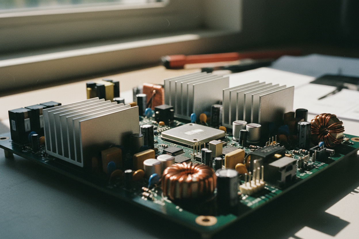
Power Stage and Protection
Under the hood, the power stage turns commands into currents. Controllers drive MOSFETs or IGBTs through gate drivers, manage dead time to prevent shoot-through, and use bootstrap or isolated supplies for high-side devices. Proper freewheel paths via body diodes or external diodes handle inductive energy; snubbers and careful layout tame ringing and reduce EMI. Stout bus capacitors buffer current pulses, while decoupling close to devices keeps edges clean. Protection is non-negotiable: overcurrent, short-circuit, overvoltage, undervoltage lockout, and thermal safeguards prevent catastrophic failures. Braking strategies matter too: regenerative braking returns energy to the supply if it can absorb it; dynamic braking dissipates it in resistors when it cannot. Fault handling should be graceful—fast shutoff, clear diagnostics, and safe restart logic. Together, these elements ensure the motor receives precise, repeatable power without compromising reliability, safety, or the electromagnetic environment around the system.
Tuning and Best Practices
Success with motor controllers comes from good selection and disciplined tuning. Size the controller for motor voltage, continuous current, and peak current with thermal headroom, and match the control method to the application's precision and dynamics. Begin with conservative ramps, verify current limits, and confirm the motor spins freely without excessive ripple. Add or refine feedback, then tune the PID: raise P for stiffness, add I for accuracy with anti-windup, and sprinkle D for damping. Use motion profiles (trapezoidal or S-curve) to limit jerk and protect mechanics. Log commanded vs. measured variables to spot saturation, friction, and resonance, and adjust filters to balance responsiveness and noise. Keep wiring short and tidy, separate power and signals, and ground thoughtfully. Document limits, fault responses, and maintenance checks. With a methodical approach, your controller will deliver stable speed, reliable torque, and enduring performance across the full life of the machine.