Motor Control Basics: VFDs and Controllers
Learn how VFDs and motor controllers manage speed, torque, and efficiency; compare soft starters, drives, PLCs, protection, wiring, and selection tips.
Foundations of Motor Control: Electric motors power conveyors, pumps, fans, and countless machines. At the heart of control are two building blocks: the speed or torque command and the device that enforces it. Basic starters simply connect line voltage, causing full inrush and fixed speed. Modern systems use variable frequency drives (VFDs) and controllers to shape motor behavior, improving efficiency, reliability, and process quality. Understanding motor characteristics is essential: AC induction motors have a speed related to applied frequency, slip delivers torque, and load curves reveal how much work the shaft can deliver without overheating. DC and synchronous machines follow different principles, yet all benefit from managed acceleration, deceleration, and protection. Control turns raw electrical power into predictable motion, coordinating speed, torque, and direction with feedback from sensors or estimates from algorithms. Done well, motor control reduces mechanical stress, quiets operation, and saves energy while giving operators precise, repeatable results across changing loads and conditions.
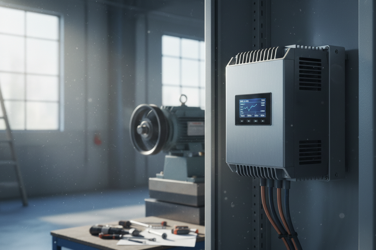
How VFDs Work: A VFD transforms fixed-frequency AC input into a variable frequency and voltage output that dictates motor speed and torque. Internally, a rectifier converts AC to DC, a DC bus stores energy, and an inverter uses high-speed switching and PWM to synthesize a near-sine output. By lowering frequency, the drive reduces synchronous speed; by coordinating voltage with frequency, it maintains magnetic flux for efficient operation. Common control modes include V/f (volts-per-hertz) for simplicity and vector control for higher dynamic performance and better low-speed torque. Benefits extend beyond speed: soft start limits inrush, reducing mechanical shock; controlled ramp times protect couplings and belts; and programmable braking options manage deceleration and stopping. Engineers also account for harmonics, cooling, and electromagnetic compatibility, applying line reactors, filters, and proper grounding when needed. When paired with a suitable motor and parameters, VFDs deliver smooth, responsive control that adapts to process demands while minimizing energy waste.
Controllers and Control Strategies: While a VFD shapes power to the motor, the controller decides what the motor should do and when. At the simplest level, contactors and soft starters handle on-off and limited current control. For precise regulation, systems use closed-loop control with a PID algorithm that compares a setpoint to feedback and adjusts speed or torque accordingly. Feedback may come from an encoder, tachometer, pressure transducer, or from sensorless vector estimation inside the drive. Controllers coordinate interlocks, sequencing, and safety, often via a PLC or embedded logic inside the VFD. Ramps, jog, and multi-speed profiles shape transitions, while limits prevent overspeed, overcurrent, and overheating. In multi-motor applications, master-follower and load-sharing strategies keep performance balanced. Thoughtful control architecture separates critical safety functions from routine automation, ensuring dependable stops and starts even during disturbances, and enabling operators to tune responsiveness, stability, and efficiency for both steady-state operation and rapid transients.
Selection and Integration Essentials: Choosing the right motor control solution starts with sizing for load, duty cycle, and required overload capacity. Match the VFD current rating to the motor and verify the application's torque-speed profile across starting, running, and braking. Environmental factors matter: enclosure rating, ambient temperature, altitude, dust, and humidity influence cooling and derating. For wiring, use proper shielded cable, short motor leads when possible, and solid grounding to reduce noise and bearing currents; add dv/dt filters or sine-wave filters for long leads or sensitive motors. Address line-side quality with reactors or filters to manage harmonics and protect upstream equipment. Commissioning steps include motor data entry, autotune, verifying rotation, setting ramps, and testing interlocks and fault responses. Integrate with higher-level controls via discrete signals or fieldbus, documenting command priorities and safe states so the system behaves predictably during power loss, emergency stops, and restarts.
Operation, Safety, and Maintenance: Reliable motor control depends on consistent practices that keep systems stable and safe. Implement preventive maintenance: inspect connections, tighten terminals, clean cooling paths, and replace worn fans and filters to preserve thermal performance. Monitor logs for fault codes like overcurrent, overvoltage, ground fault, or stall, and investigate root causes rather than repeatedly resetting. Tune PID gains to avoid hunting and oscillation, and adjust ramps to prevent nuisance trips during acceleration or deceleration. Use built-in protections such as thermal models, current limits, and safe torque off to reduce risk during service. Verify grounding and shielding to minimize electromagnetic interference with sensors and networks. Track energy use and load trends to spot bearings that are wearing out, misaligned belts, or oversized equipment that invites inefficiency. Clear labeling, updated documentation, and operator training ensure that when the unexpected happens, the drive and controller respond in a controlled, predictable way.